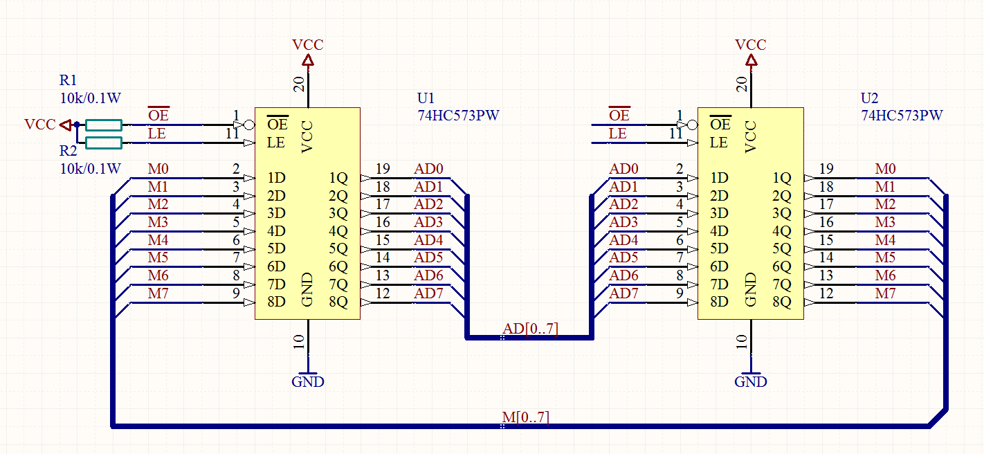


The top menu shows the wire, GND, library, place port, place text, move, drag and select options. Press and hold the right click to “Pan” and Left Ctrl + Right click will zoom in and out. Now find the component in library and place on schematic one by one. Unzip it and copy paste the folders inside C:\Users\Public\Documents\Altium\AD18\Library\ this folder. You can add the manufacturer libraries available directly from Altium website. After saving you can now start placement of components from library located on the right most menu. Then you can save your PCB project and schematic file with *.PrjPcb and *.sch extensions respectively. An expert in the software having knowledge in the said software will professionally capture’s the design in schematic window.įile > New > Project > PCB Project then right click on the project to “ Add New to Project” > Schematic This process is called schematic capture. Now the design on paper will be transferred to CAD software like Altium. This gives the clear understanding to the designer to know what he is looking for. The first step in the process of giving the physical shape or turning the idea into reality is to do manual design or hand sketch on paper. Request PCB Manufacturing & Assembly Quote Now Schematic Capture


 0 kommentar(er)
